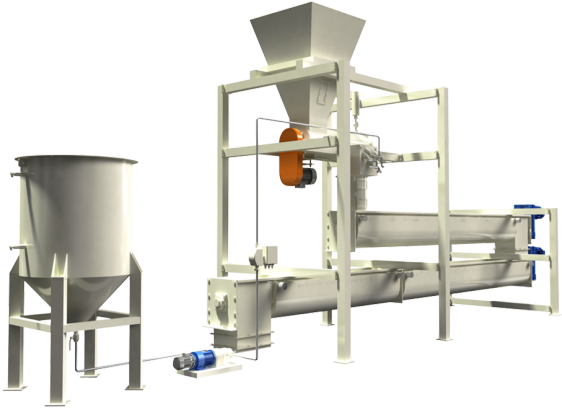
The fat addition machine enriches the feeds that need a high percentage of fat, such as poultry feed, without injuring the compactness of the final product. The cycle begins after the sifting of the pellet that makes it homogeneous, well filled and dry, with a fat percentage ranging from 2 to 7%. The production varies from 5 to 30 t / h , depending on the size of the machine.
The production varies from 5 to 30 t / h , depending on the size of the machine.
- The pellet flows in through a hopper
- It goes into an extraction screw. Its speed is set by an inverter that controls the capacity, according to the level set on the capacity probe.
- The flow is constantly weighed by a weighing bin. This electronic device measures the force applied to an object (usually a mechanic component) through the monitoring of an electric signal modified by the deformation that the force induces on the component
- The fat is sprayed on the pellet by a spraying chamber connected to a 600L tank, spray the shortening or vegetable oil.
- The pellet is conveyed through two screw feeders where it stays for a period of time which allows the oil to penetrate inside the cube and homogenize uniformly, thanks to the rotary movement and the fins on the surface. Heating is carried out by means of the steam flow, which circulates within a piping system external to the screw jacket. Heating serves to keep the augers clean. The temperature of the pellets rises by approximately 2, 3 degrees.
- The material comes out and can be directly bagged.
The line is made of:
– Painted steel dosing system consisting of
- Hopper
- Capacitive probe, which regulates the flow rate based on the pre-set level
- Variable flow dosing screw with integrated inverter gearmotor with 3 kW power
– Hoopers in painted steel with variable diameter and length depending on the capacity of the machine. Pellet travel time: 12 meters in one minute.
- Designed to be heated with tube bundles inside which the steam circulates, installed adherent to the screw, with steam pressure 1.5/2 bar
- Condensate recovery
- Insulation using rock wool wrapped in a suitably shaped and riveted sheet of galvanized sheet metal
- 5.5 kW motor varies according to the size of the machine
Technical specifications
The table below lists the models on the market.
| Modello | Engine power | Hooper Diameter | Lenght | Hooper power | Capacity |
|---|---|---|---|---|---|
| Lop-F 10 | 3 kW | 300 mm | 10m | 3kw | 10 T/h |
| Lop-F 20 | 3 kW | 300 mm | 14m | 4kw | 20 T/h |
| Lop-F 30 | 3 kW | 350 mm | 20m | 5,5kw | 30 T/h |
The liquid dosing unit consists of:
- Liquid tank with capacity of approximately 600 kg, built in AISI 304 and designed for steam heating (maximum pressure 1.5/2 bar)
- Valves and nozzles for liquid interception
- Air spray injection valve
- Shut-off valve for cleaning pipes and spray nozzles at the end of production
- Volumetric pump
- Mass flow meter with 4-20 MA.
- Signal proportional to the dosage of the pellet flow
- 1.5 kw servo-ventilated gearmotor
The spraying chamber made of AISI 304 is made of:
- Two spray ramps with nozzles (the nebulization is with low pressure compressed air 0.5 bar)
- The spraying chamber is heated externally with an adherent tube in which the steam circulates at 1.5/2 bar
Optional
Electronic control panel for the dosing of the liquid and for the motors of the system


